Chapter 8.8 Kirchhoff’s laws with applications (Electromagnetism)
Circuit – a circuit is a closed loop conducting path in which an electrical current flows.
English
Last updated
Sat, 15-Jun-2024
Circuit – a circuit is a closed loop conducting path in which an electrical current flows.
English
Last updated
Sat, 15-Jun-2024
Common DC Circuit Theory Terms:
• Circuit – a circuit is a closed loop conducting path in which an electrical current flows.
• Path – a single line of connecting elements or sources.
• Node – a node is a junction, connection or terminal within a circuit were two or more circuit elements are connected or joined together giving a connection point between two or more branches. A node is indicated by a dot.
• Branch – a branch is a single or group of components such as resistors or a source which are connected between two nodes.
• Loop – a loop is a simple closed path in a circuit in which no circuit element or node is encountered more than once.
A Typical DC Circuit
Kirchhoff’s First Law – The Current Law, (KCL)
Kirchhoff’s Current Law or KCL, states that the “total current or charge entering a junction or node is exactly equal to the charge leaving the node as it has no other place to go except to leave, as no charge is lost within the node“.
In other words the algebraic sum of ALL the currents entering and leaving a node must be equal to zero, I(exiting) + I(entering) = 0. This idea by Kirchhoff is commonly known as the Conservation of Charge.
We can use Kirchhoff’s current law when analysing parallel circuits.
Kirchhoffs Second Law – The Voltage Law, (KVL)
Kirchhoffs Voltage Law or KVL, states that “in any closed loop network, the total voltage around the loop is equal to the sum of all the voltage drops within the same loop” which is also equal to zero. In other words the algebraic sum of all voltages within the loop must be equal to zero. This idea by Kirchhoff is known as the Conservation of Energy.
The sum of all the voltages around a loop is equal to zero.
v1 + v2 + v3 - v4 = 0
We can use Kirchhoff’s voltage law when analysing series circuits.
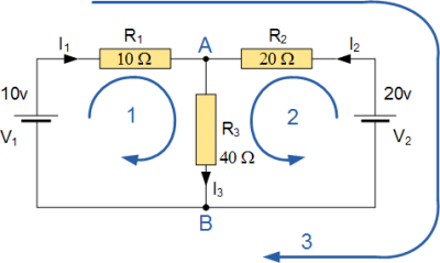
Problem: Find the current flowing in the 40 Ω Resistor, R3
Soln.: The circuit has 3 branches, 2 nodes (A and B) and 2 independent loops.
Using Kirchhoff’s Current Law, KCL the equations are given as;
At node A : I1 + I2 = I3
At node B : I3 = I1 + I2
Using Kirchhoff’s Voltage Law, KVL the equations are given as;
Loop 1 is given as : 10 = R1 I1 + R3 I3 = 10I1 + 40I3
Loop 2 is given as : 20 = R2 I2 + R3 I3 = 20I2 + 40I3
Loop 3 is given as : 10 – 20 = 10I1 – 20I2
As I3 is the sum of I1 + I2 we can rewrite the above equations as;
Eq. No 1 : 10 = 10I1 + 40(I1 + I2) = 50I1 + 40I2
Eq. No 2 : 20 = 20I2 + 40(I1 + I2) = 40I1 + 60I2
Using equations 1 & 2 we have
I1 = -0.143 Amps
and
I2 = +0.429 Amps
As : I3 = I1 + I2
I3 = -0.143 + 0.429
I3 = 0.286 Amps
The voltage across the resistor R3 is given as : 0.286 x 40 = 11.44 volts


Study any topic, anytime. explore thousands of courses for the lowest price ever!