Course description
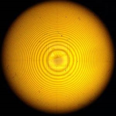
To produce Newton’s rings a plano-convex lens of large radius of curvature is placed on a glass plate so that its convex surface faces the plate, a thin air film of progressively increasing thickness in all directions from the point of contact between the lens and the glass plate is very easily formed (Fig. 22 a). The air film thus possesses a radial symmetry about the point of contact. When it is illuminated normally, preferably with monochromatic light, an interference pattern consisting of a series of alternate dark and bright circular rings (Fig. 22 b), concentric with the point of contact is observed.
(a) (b)
Fig 22
Theory of Newton’s rings:
Let us consider a ray of monochromatic light AB incident at the point B on the upper surface of the air film (Fig. 23). One portion of the ray is reflected from point B and goes upwards along BR. The other part refracts into the air film along BC. At point C, part of the light is again reflected along CB1R1. The two reflected rays along BR and BCB1R1 are derived from the same source and are coherent. They will produce constructive and destructive interference depending on their path difference. Let t be the thickness of the film at the point B1 and let the tangent to the convex surface be inclined at an angle θ with the horizontal.
Let us draw B1D and B1E perpendiculars to BD and BC respectively.
Now the optical path difference between the reflected rays BD and BCB1 is expressed by
[ ∆ = µ (BC + CB1) – BD [ µ=(Original distance/Aparent distance ]
Fig 23 ∆ = µ (BE + EC + CB1) – BD ---------------------------(i)
where µ is the refractive index of the film with respect to air.
Now,
[
From equ. (i) ∆ = µ (BE + EC + CB1) – µ BE = µ (EC + CB1) --------------------(ii)
Let BN and CN be the normal to the upper and lower surfaces of the film respectively. Hence we get,
In the Fig. 23, B1M is perpendicular from B1 on the lower surface of the air film and the extension of BC intersects it at O. Thus we have the relation
Also
Thus B1OC is an isosceles triangle. Hence CB1 = CO
Equ. (ii), therefore, reduces to ∆ = µ (EC + CO) = µ EO = µ B1O cos (r + θ) [∴ cos (r + θ) = EO/B1O]
If t is the thickness of the film at the point B1 and B1M = MO = t.
∴ ∆ = µ 2t cos (r + θ) = 2µt cos (r + θ) [Where, B1O = 2 B1M = 2 t]
We still have to consider a path difference of introduced as a result of reflection at the point C with an abrupt phase reversal of ᴫ. Where λ is the wavelength of light in air.
Then the total optical path difference between the two rays,
∆ = 2µt cos (r + θ) ± λ/2
For constructive interference, 2µt cos (r + θ) ± λ/2 = nλ
2µt cos (r + θ) = (2n -1)λ/2 -------------- (iii) bright
The minus sign has been selected since n cannot have a value of zero for bright fringes seen in reflected light.
For destructive interference, 2µt cos (r + θ) ± = (2n ±1)λ/2
2µt cos (r + θ) = nλ ------------------(iv) dark
In practice, a thin lens of extremely small curvature is used and hence the angle θ becomes negligible. Furthermore, the experiment is so designed that the light is incident almost normally on the film and and therefore cos r = 1. Accordingly Eqns. (iii) and (iv) reduce to
2µt = (2n -1)λ/2 --------------------------(v) bright
and 2µt = nλ --------------------------(vi) dark
Let us now compute the radius of any ring. Let R be the radius of curvature of the convex surface as shown in the Fig. 24. From the right angled triangle OFB1, we can get the relation
R2 = rn2 + (R - t)2
rn2 = 2Rt – t2
where rn is the radius of the nth circular ring corresponding to the constant film thickness t. Here t is extremely small that t2 may be neglected compared to 2Rt. Then
t=(r_n^2)/2R
Substituting the value of t in equs. (v) and (vi), we have
Fig 24
rn2 = (2n -1)λR/(2µ) --------------------(vii) bright
rn2 =nλR/µ -----------------------(viii) dark
Now the square of the diameters of the bright and dark rings are, therefore, given by
D_n^2=2(2n-1)λR/µ ------------------------(ix) bright [〖∵D〗_n^2=〖(2r_n)〗^2 ]
D_n^2=4nλR/µ ----------------------(x) dark
Determination of wavelength:
(a) (b)
Fig. 25
Let us consider the nth order ring (Fig. 25 b). For an air film µ = 1. Therefore, the square of the diameter of the nth order bright or dark ring will be
D_n^2=2(2n-1)λR ------------------------ (xi) bright
D_n^2=4nλR ---------------------------(xii) dark
Now we have to take another ring, p ring from this nth ring onwards. The diameter of this (n+p)th ring is also measured. Thus we have
D_(n+p)^2=2[2(n+p)-1]λR--------------------(xiii) bright
D_(n+p)^2=4(n+p)λR -----------------------(xiv) dark
Now applying {(xiii) - (xi)} and {(xiv) - (xii)}; we will get for both the dark and the bright rings the relation
D_(n+p)^2-D_n^2=4pλR
or, λ= (D_(n+p)^2-D_n^2)/4pR-----------------------(xv)
Eqn. (xv) is used to compute the wavelength λ of the monochromatic light that employed to illuminate the film.
Determination of the radius of curvature of the lens:
The eqn. (xv) can be rearranged as
R= (D_(n+p)^2-D_n^2)/4pλ------------------------(xvi)
Thus, if the wavelength λ of the light used is known then the eqn. (xvi) can be used to determine the radius of curvature of the surface of the lens in contact with the plane glass plate.
Problem 2: In a Newton’s ring experiment, the diameter of the 4th and the 8th rings are 3.21 mm and 4.55 mm respectively. If the radius of curvature of the surface of the convex lens in contact with the plane glass plate is 105.76 cm then what will be the wavelength of light used in this experiment?