Course description
The modification of light intensity due to superposition of two or more beams of light is known as interference of light. The interference is said to be constructive or destructive when the resultant intensity is respectively more or less than that given by one beam alone (Fig. 13).
Fig. 13
Constructive and destructive interference:
Destructive interference is occurred when two waves neutralize each other (Fig. 14 a).
Constructive interference is occurred when two waves reinforce each other (Fig. 14 b).
(c)
Fig. 14
Coherent sources:
To get the stationary interference pattern, the two sources must start either exactly in phase or with a constant phase difference. This can be possible only if the two sources are derived from a single parent source. Therefore, wavelength, period and phase of the light of these two sources will be same (Fig. 15).
Fig. 15
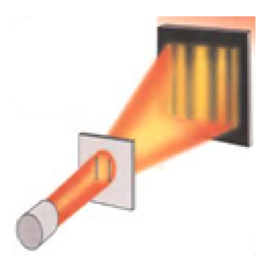
Young’s double-slit experiment:
(a) (b) (c)
Fig. 16
Let us consider two coherent sources of light S1 and S2. Let P be any particle in the medium at distances x1 and x2 from S1 and S2 respectively as shown in Fig. 16 (a). Figs 16 (b) and (c) show the practical examples.
Let y1 be the displacement of the particle P due to the waves emanating from the source S1 alone at any instant of time and let y2 be the same due to waves coming from source S2 alone at the same instant of time. If y be the resultant displacement of the particle P at that instant of time then according to principle of superposition
y = y1 + y2
If the phase of the two waves at the instant of their moving out be wt, then the progressive waves will be
Now,
Theory of interference fringes: expression for the width of a fringe:
In Fig. 17, S1 and S2 are two narrow parallel slits separated by a distance d and act as two coherent sources of light. Let PR be a screen placed at a distance D from the sources. At point O on the screen, which is equidistance from the sources, the path difference of the waves is zero and they arrive in phase. Hence O will be a bright point.
Let the point P, located on the screen at a distance xn from the point O, represent the nth bright fringe. S1Q and S2R are perpendiculars on the screen from the points S1 and S2 respectively.
From the right angled triangle S1PQ,
Fig 17
S1P2 = S1Q2 + PQ2 = D2 + (xn – OQ)2 = D2 + (xn – d/2)2 -------------------(i)
Similarly, from S2PR,
S2P2 = D2 + (xn + d/2)2 --------------------(ii)
Subtracting eqn. (i) from (ii)
S2P2 - S1P2 = D2 + (xn + d/2)2 - D2 - (xn – d/2)2 = 2xnd
(S2P + S1P) (S2P - S1P) = 2xnd
(S2P - S1P) = 2xnd / (S2P + S1P) -------------------------(iii)
Both xn and d are small compared to D, therefore, S2P = S1P ≈ D or, S2P + S1P ≈ 2D
Eqn (iii) can be written as
(S2P - S1P) = 2xnd / 2D = xnd / D -------------------------------(iv)
Here, (S2P - S1P) is the path difference of the light waves at the point P and according to the condition of interference, must be equal to nλ, since P represents the nth bright fringe. Thus, (S2P - S1P) = xnd / D = nλ
or, xn = nλ D/d ---------------------------(v) where n = 0, 1, 2, 3, -------------
Here, n = 0 corresponds to the central bright fringe, n=1 gives the distance of the first bright fringe, n=2 gives the distance of the second bright fringe and so on.
Now, substituting n = n+1 in eqn. (v) we get, xn+1 = (n+1)λ D/d --------------------------(vi)
where xn+1 is the distance of the (n+1)th bright fringe from the central bright fringe.
Subtracting eqn. (v) from (vi), we get, xn+1 - xn = (n+1-n) λ D/d = = constant------------------------(vii)
Here, xn+1 - xn is the distance of separation between the nth and (n+1)th bright fringes (i.e., any two consecutive bright fringes) and all bright fringes are equally spaced.
It can also be seen that the distance between two consecutive dark fringes is same and equally spaced and equal to .
Thus the distance between any two consecutive bright or dark fringes which includes one dark and one bright fringe is same. This distance is called the fringe-width (X) (Fig. 18).
Hence, the fringe-width, X = λD/d .
Fig 18
Interference by multiple reflections: (Interference due to reflected light from a constant thickness film)
Fig. 19 shows a thin transparent film of uniform thickness t and refractive index µ, bounded by two parallel surfaces MN and PQ. A ray AB of monochromatic light is incident on the upper surface at the point B. A part of it is reflected along BC and a part is refracted along BD. The refracted beam is again partly reflected at the point D back into the medium along DE and the rest refracts along DL. The ray along DE suffers both reflection and refraction at point E on the upper surface MN. The refracted ray goes along EF. Similar reflections and refractions will produce a number of parallel rays in the surrounding medium both above and below the thin film.
Consider the rays BC and BDEF. They are both derived from the single beam AB and hence satisfy the condition for producing interference (coherent source). Whether they (when collected by lens or eye) will interfere constructively or destructively.
Fig 19
Interference due to reflected light from a varying thickness film (wedge shaped film)
Suppose the film is not parallel sided but is in the shape of thin wedge. The thickness of the film will continually increase from E to A (Fig. 20). The monochromatic light AB is incident on the upper surface at the point B and will give rise to two light waves- The directly reflected ray along BR and the internally reflected ray along B/R/. The rays BR and B/R/ are, therefore, coherent and capable of producing interference. However, the two interfering rays do not reach the eye along parallel paths but appear to diverge from a point Q. Constructive of destructive interference, therefore, occurs at the point Q, which is, however, virtual.
Fig 20
Fresnel bi-prism:
(a) (b) (c)
Fig. 21
The bi-prism is constructed from a single plate of glass by suitably grinding and polishing it. The obtuse angle of the prism is only slightly less than 1800 (may be 179020/ for a thin bi-prism) and the other two angles are equal and may be 20/ each. When light is allowed to fall symmetrically on the bi-prism, the refracting edge B divides the incident wavefront into two parts as shown in Fig. 21 (a). The one which is passing through the upper half ABD of the bi-prism is deviated through a small angle towards the lower half of the diagram and appears to diverge from the virtual source S1. Secondly the one which passes through the lower half CBD of the bi-prism is also deviated through a small angle towards the upper half and appears to diverge from the virtual source S2. S1 and S2 being the image of the slit S, obviously function as coherent sources in this experiment. Moreover, the two emergent wavefronts intersect at small angles and hence the fundamental condition of interference is satisfied. If a screen is placed on the right of the bi-prism, interference fringes of equal widths are produced in the overlapping region between E and F of the two emergent beams. Figs 21 (b) and (c) show the fringes and experimental setup respectively.

