Course description
2.3 Bending of beam & Cantilever:
Beam: A rod or a bar of uniform cross-section, circular or rectangular, the length of which is very much greater than its thickness is called a beam. When at the one end of a fixed beam is loaded, it bends due to the moment of the applied force (Fig. 15).
Fig. 15 a
Fig. 15 b
Deformation by bending:
In Fig. 16 the layer near the convex side AB becomes extended and the layer near the concave side CD becomes compressed. In between these two portions, there is a layer or surface, in which the material of the beam is neither compressed nor extended, the original length EF remaining constant. This surface layer of no deformation is called the neutral surface of the beam. The line EF which is the line of intersection of the neutral layer and the plane of the applied couple is known as the neutral axis.
Fig. 16
Situation is given as in Fig. 16. In the unstrained condition of the beam m/n/ = mn.
Now, mn = Rθ and m/n/ = (R + x)θ.
Therefore, increase in length, m/n/ - mn = (R + x)θ – Rθ = xθ.
Strain =xθ/Rθ=x/R
Thus the strain in a layer is directly proportional to its distance from the neutral axis.
Bending moment:
(a) Fig. 17 (b)
Load and opposite force form a couple called bending couple or applied couple which tending to bend the section clockwise (Fig. 17).
External bending moment = Load × distance between load and opposite force = W. (L-X).
Inward pull and outward pull form another couple which tends to bend the section in a direction opposite to that due to the applied couple. This couple resists the bending of the beam by the applied couple. In the equilibrium position its moment (Internal) is equal in magnitude, though opposite in direction to that of the bending or applied couple. The moment of this couple is called internal bending moment and is equal to
W. x = Pull (load) Χ distance between OO/ and AB line. Here OO/ is the neutral surface or axis.
ABCD is a beam and fixed at the end AD and loaded (within a elastic limit) with a weight W at its free end. In its equilibrium position the load W and opposite force W forms a couple tending to bend the section clockwise. This couple is called bending couple. The layer above the neutral axis OO/ being elongated and hence in a state of tension, exert an inward pull and the layer below the OO/ axis being shortened and exert an outward pull. These inward and outward pull form a pair of equal and opposite forces or a couple which tend to bend the section in a direction opposite to that due to applied couple, i.e., in an anticlockwise direction.
As this couple opposes or resists the bending of the beam by the applied couple and since in the equilibrium position its moment is equal in magnitude, though opposite in direction, to that of the bending couple, the moment of this couple is referred to as the bending moment (M).
Expression for bending moment of a beam:
Fig. 18
Let us consider a small element m/n/nm of the beam bents in the form of an arc of a circle of radius R (Fig. 18). The neutral surface mn subtends an angle θ at the curvature O. The line mp be drawn parallel to nn/. Therefore, mn = pn/. Then the extension of length pn/ = pm/.
Tensile strain = (pm^/)/mn
If α is the area of cross-section of the filament and F is the applied force, tensile stress = F/α.
Now the Young’s modulus for the material of the beam is given by
Y = (F/(α ))/((pm^/)/mn)
From the Figure, pm/ = xθ and mn = Rθ
Y =(F/(α ))/(xθ/Rθ)=FR/αx ; F =Yxα/R
The moment of this force about mn==F.x=Yx^2α/R
Therefore, the total moment of all the forces about mn, or the bending moment of the beam,
Where,Ig=∑ 〖αx〗^2 is the geometric moment (area moment of inertia) of the given cross-section.
This bending moment balances the moment of the external force acting at the section.
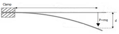
Cantilever:
Fig. 19
Cantilever: A beam rigidly fixed at one end and loaded at the other is called a cantilever. Fig.19 shows the implementation of cantilever.
Fig. 20 (a)
Expression for the depression:
In Fig. 20 (a), AB is a cantilever of length L, having one end rigidly fixed at A and other end B loaded (within the elastic limit) with a weight W, so that the end B is bent. The neutral position OO/ will now shift to OO//. Therefore, the depression (or deflection) of the loaded end is O/O//.
From the above figure it is clear that the external bending moment acting on the section PO/ due to load W = W × PO// = W (L-X).
We know for equilibrium of the beam, this moment must be balanced by the internal bending moment of (YI_g)/R . Now at equilibrium
W (L-X) = -----------------(i)
Let DP and EQ be tangents to the curve at P and Q respectively.
From the figure: PQ = δx = R dθ; or, R = δx/dθ
Here dθ is the change in slope of the tangents from P to Q.
Slop is given by dy/dx. Therefore, dθ = 〖(dy/dx)〗_Q- (dy/dx)p [Fig. 20 (b)]
and the rate of change of slope with respect to distance = d/dx (dy/dx)=(d^2 y/dx^2) = Change in slope for unit distance.
Therefore, the change in slope for δx distance
=(d^2 y)/(dx^2).δx=dθ
and δx = R dθ =R.(d^2 y)/(dx^2).δx
If R.(d^2 y)/(dx^2)=1 , then 1/R=(d^2 y)/(dx^2)
Now equation (i) reduces to W(L-X)=YIg(d^2 )/(dx^2)
(d^2 y)/(dx^2)= W-YIg(L-X)
Integrating we have
dy/dx= W/(YIg(LX-x^2/2)+C1 -----------(ii)
Where, C1 is a constant of integration.
Since the end A is fixed we have dy/dx=0 at x = 0.
Therefore, C1 = 0
Problem 3: A uniform rod of 1 m length is clamped horizontally at one end. A weight of 0.1 kg is loaded at the free end. Calculate the deflection of the midpoint of the rod. The diameter of the rod is 0.02 m. (Y = 1010 N/m2)
Soln.: We know the depression at a distance of x from the clamped end is
Here x is given L/2 (L = 1 m); W = mg, (m = 0.1 kg).
For the circular beam cross-section of radius r, (see below with Fig. 21)
Following the Fig. 21:
Fig. 21
Therefore,
Properties of Matter
Q1. What will be the chemical composition of a matter with changing the state of it?
Q2. Discuses in brief about the changing properties of different states of a substance.
Q3. Differ the crystalline and non-crystalline solids.
Q4. Give some examples for occurring plasma state.
Q5. Give some examples for being used the special properties of matter.
Q6. Define Elasticity, Perfectly elastic body, Perfectly plastic body, Load, Stress and Strain.
Q7. Why are there different types of stress and strain?
Q8. State Hooke’s law
Q9. Explain the general behavior of material under stress with reference to the diagram of stress-strain.
Q10. What type of modulus is referred to as incompressibility?
Q11. Name two states of matter where the elasticity they possess is only bulk modulus.
Q12. When are two modulus (modulus of rigidity and Young’s modulus) going to similar? But what are the differences exist between them?
Q13. State Poisson’s ratio.
Q14. What is meant by a beam? Explain the terms: neutral surface and neutral axis with a diagram.
Q15. Show that the strain in a layer is directly proportional to its distance from the neutral axis.
Q16. Explain the external and internal bending moment of a beam with a figure.
Q17. Derive an expression for the couple required to bend a uniform straight metallic strip into an arc of a circle of small curvature.
Q18. What is cantilever?
Q19. Obtain an expression for the depression at the free end of a thin light beam clamped horizontally at one end and loaded at the other.